


 Reply With Quote
pm slydar, or wait for his response here but im you wont be able to get the suspension into a useable stroke range with the casing cut that short....


I asked this question on club4ag but I never really got a solid response.
Has anyone done this?
I'll be in the process of making coilovers, Ground Control sleeves and springs, AGX's, etc. I've always seen people cut out 40mm from the original strut casing, AND THEN put a 20mm spacer at the BOTTOM, so that it sits flush with the top of the strut.
So I'm wondering, instead of having a 20mm spacer at the bottom, why not just cut out that extra 20mm from the strut casing and have NO spacer? I'm by no means a suspension expert, I can barely put shit together, but thinking about it...
Spacer at the bottom means shock is raised 20mm
Efficient shock travel will be raised 20mm
So if the spacer is eliminated, that means it'll sit lower, and the optimal shock travel will be lower. This would mean that the car would have to sit lower in order to be in that range, correct?
I'm looking for someone who's actually done this, but please people, chime in if you can.
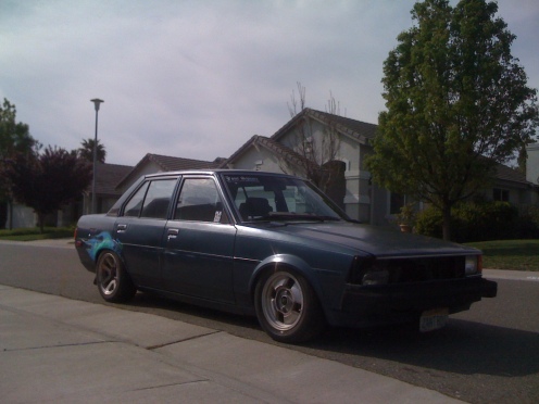
For reference, this is how my car sits currently:
Stock non-cut strut casings in the front, NO springs, so it's just sitting on the shock haha. I'm trying to achieve this height and still have decent shock travel... if that's possible.
Cheers!
-Lucky/Laurante/Teh Luckinator
*e7*club! ke70's, te72's! check out our build threads! link below.
http://www.e7club.org

pm slydar, or wait for his response here but im you wont be able to get the suspension into a useable stroke range with the casing cut that short....
RIP Carly - a smile to light the world.
06/07/2011
bloody hell thats low.
problem might be that when you cut that much off, you are gonna need a monster RCA to get the LCA to sit where it should, otherwise you are gonna have some epic bumpsteer.
im almost finished my ae86 coilovers, i bought them already cut/welded, and they fit ae92 shocks (~330mm) in without any spacer....so i dunno if they are gonna be alright or not. i got some 40mm RCA's, only cause they were cheap...
this is my first experience with ae86 gear, but it cant be as low as the s13 stuff that is in there.
In faith there is enough light for those who want to believe and enough shadows to blind those who don't.
- Blaise Pascal

ok so the new dampner has a 60mm shorter body correct? by memory I worked out that for every incriment the car is lowered the dampner body length should be shortened 2/3 the amount to keep the valves in the middle. Your car at a guess looks 150mm lower, lower than unsagged stock that is. So you need a dampner body thats 100mm lower but I could be getting mixed up here. Either way I can't see 40mm out of ideal in either direction being much of an issue. Afterall if you look at off the shelf big name suspension packages they use the standard casing and shaft length with springs that are about 50mm lower, although this could be a cost cutting thing. If I could be bothered and you want me to I will work it out again to make sure I am giving the right figures.
ke70dave: I am sure you already know this but I will explain for the others reading; I have found long RCA's are either not available in decent thicknesses or they just don't fit. As a guess I would say they are Tarago front wheels, not sprinter so 14". This would mean with a blocked off grease nipple the max thickness is about 40mm or so, I am a bit unsure as it's been many years since I was playing with that stuff under my car. One other thing no change in height causes bump steer in our type of cars, well unless you have stuffed it all up with S13 gear that is. That's because bump steer is caused by different arc's of axis between the lower control arm and the steering arm's. What you are talking about though is the effect of the front sideways roll center being pushed massively downwards, that's some kind of bad Voodoo stuff that I don't get.
Last edited by Sam-Q; 21st April 2010 at 08:08 PM.
My website: SQ Engineering - 4AGE and 3SGE upgrade/replacement parts
- SQ Engineering on facebook -
Please e-mail to contact me instead of sending a private message on here.

I once did what you surgest and cut 60mm from the strut rather than just 40mm + a 20mm spacer. The negative effect this has is that you have reduced droop. When I jacked the front of the car up, the front wheels would hardly droop at all from normal position. On the bumpy roads in the country, the front wheels may leave the ground for a moment over a crest or bump, which is not good for grip. And if you lower the car so much that you do have some droop, then you have other issues with the car being so low. Legal ride height in Australia is 100mm off the ground. Also bump steer is effected by the angle of the lower control arm...
how? I don't think it is
My website: SQ Engineering - 4AGE and 3SGE upgrade/replacement parts
- SQ Engineering on facebook -
Please e-mail to contact me instead of sending a private message on here.


ackerman principal google this one boys ... bump steer will take over on this for sure
2 in the pink 1 in the stink
the offet acherman arms are from factory offset by the steering rack being shorter than the lower control pivots by the same proportial degree. I think your wrong.
My website: SQ Engineering - 4AGE and 3SGE upgrade/replacement parts
- SQ Engineering on facebook -
Please e-mail to contact me instead of sending a private message on here.
when the car is low down like that everything will change a few degrees ...
low control arm will go up a bit there for makin bump steer off the chain
2 in the pink 1 in the stink
Ackermann steering geometry is a geometric arrangement of linkages in the steering of a car or other vehicle designed to solve the problem of wheels on the inside and outside of a turn needing to trace out circles of different radii. It was invented by the German Carriage Builder "Lankensperger" in 1817, then patented by his agent in England Rudolph Ackermann (1764–1834) in 1818 for horse drawn carriages. Erasmus Darwin may have a prior claim as the inventor dating from 1758. [1]
A simple approximation to perfect Ackermann steering geometry may be generated by moving the steering pivot points inward so as to lie on a line drawn between the steering kingpins and the centre of the rear axle. The steering pivot points are joined by a rigid bar called the tie rod which can also be part of the steering mechanism, in the form of a rack and pinion for instance. With perfect Ackermann, at any angle of steering, the centre point of all of the circles traced by all wheels will lie at a common point. Note that this may be difficult to arrange in practice with simple linkages, and designers are advised to draw or analyze their steering systems over the full range of steering angles
2 in the pink 1 in the stink
 Posting Permissions