Page 1 of 2 1 2 LastLast
Results 1 to 10 of 15

Thread: Correctable flaw in the 20v intake design?

  1. #1
    Moderator Sam-Q's Avatar
    Join Date
    Dec 2008
    Name
    Sam
    State
    VIC
    Location
    Endeavour Hills
    Country
    Australia
    Posts
    4,242

    Default Correctable flaw in the 20v intake design?

    I originally posted this on toymods and there sure is some debate over the result, here is the original thread:


    so for the interest sake I am posting this here as well:


    I have been thinking about doing an unsual modification to my 20v intake. Even since I started doing some matchporting on my first spare 20v head years ago I thought it was odd that there was a decent step from where the intake manifold meets the head. Sure I did some matchporting to have a nicer radius but its still roughly a 15 degree bend in the manifold port to the intake port. I have been told anything more than a 7 degree change in direction without a radius will cause flow seperation of the laminar layer causing eddies in region just after the angle change, effectively reducing the cross sectional area and screwing with the harmonics. But I must stress aerodynamics isnt something I understand very well so I could of just said something stupid.

    I hate to quote second hand info but I have heard that a worklshop in Vic somewhere did some testing on a flowbench and gained a 10% flow gain by making the inlet path in a straight line. Assuming this is true I still have no idea what this means for real world use.

    I have started making an angled spacer to do the same on my engine and I am wondering if its an effert of futility. I will have it so the original manifold bolts up in such a way that I will be able to open a throttle and look down inside to see my three inlet valves. It will be made from one main block of aluminium and smaller block for a clamp (dont ask).


    Anyone have any thoughts if there might be a difference in the real world by doing such a change.

    Any further questions and theories?


    Thanks to Shelldrake for this idea and info.
    My website: SQ Engineering - 4AGE and 3SGE upgrade/replacement parts

    - SQ Engineering on facebook -

    Please e-mail to contact me instead of sending a private message on here.

  2. #2
    User fantapants's Avatar
    Join Date
    Dec 2008
    Name
    Pat
    State
    TAS
    Location
    Other
    Country
    Australia
    Posts
    1,635

    Default

    i think its dans toys i the states that seem to have quad throttles on 3s motors that come out at a massive angle... i assume for something similar to what your looing at man?

    for my two cents, id say the inlet track isnt long enough for the laminar layers to produce much of an effect.could be wrong but vanes or air directional tools might be a more prosperous method?

    let me know how the results go mate

    RIP Carly - a smile to light the world.
    06/07/2011

  3. #3
    Moderator Sam-Q's Avatar
    Join Date
    Dec 2008
    Name
    Sam
    State
    VIC
    Location
    Endeavour Hills
    Country
    Australia
    Posts
    4,242

    Default

    that is also what someone else has commented, however maybe it would just reduce turbulence or a potential partial reversion wave when theres a pulse going up the inlet port?
    My website: SQ Engineering - 4AGE and 3SGE upgrade/replacement parts

    - SQ Engineering on facebook -

    Please e-mail to contact me instead of sending a private message on here.

  4. #4
    Veteran Jonny Rochester's Avatar
    Join Date
    Dec 2008
    Name
    Jonathan
    State
    TAS
    Location
    Hobart
    Country
    Australia
    Posts
    2,660

    Default

    A fair few engineers on Toymods I see.

    We need to confirm your situation. Do you want the most power from your N/A 1600 20v motor? If yes, then do you want the most cost-effective power gains that you can afford, upgrading only when you have the money? How far along this list are you now?

    1. put 20v in car, RWD. Done
    2. run on standard EFI, see how it goes. Done, I assume. Dyno reading?
    3. cold air and decent exhaust. Done.
    4. get aftermarket computer and tune. (should be exact same power)
    5. remove VVT, adjustable cam gears, retune (could get slight increase)
    6. get big camshafts and new valve springs. retune and play with timing. (should get a massive difference. towards 195 or 200hp with the right combo?)
    7. rebuild for more revs. Conrods etc...

    So you have done all this, and now you want a tiny bit more? If yes, then you need a flow-bench. Which you can make. And you probably want a spare head or two.

  5. #5
    Moderator Sam-Q's Avatar
    Join Date
    Dec 2008
    Name
    Sam
    State
    VIC
    Location
    Endeavour Hills
    Country
    Australia
    Posts
    4,242

    Default

    great post Jonny, good to see someone is looking at the bigger picture.

    2: yes a modified version of the stock ecu (standard map of course) didnt do a dyno reading and didnt see the point. Developed a problem later on that through a process a of elimination later was found to be in the loom itself. Was unpredictable and it sucked

    3: I am going to try something further with the cold air duct but yeah otherwise for the greater part your right its done.

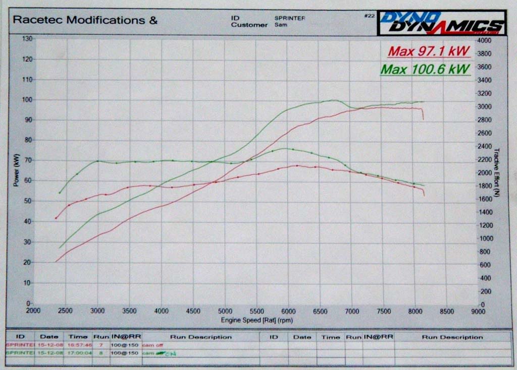
    4: Got the wolf V4 fitted. I am tottaly confused why you think it would have the same power seeing that 20V ECU's are known to have completely rich mixtures above either mid load or mid revs and also that everyone has gained significant power increases with a new tune. This also includes me. See the pic below:


    5 + 6: I am unsure of having an engine that has long agresive duration camshafts and therefore have to get rid of my VVT. I respect you for going down that road but I think at most I will go to 270 degree cams to still keep the VVT. I do however have an adjustable T3 gear that I will fit to the exhuast gear and experiment with.

    7: Later, I have some spool rods and some ARP main studs sitting here ready.

    I do plan on still doing the following: better cold air intake, a new low mount intake airbox, coilpacks, more intake and exhaust tuning, putting my modded blacktop head on and some bottom end work.

    The reason I am thinking about doing this now is I have the resources available right now, would be cheap for me to do and would work with any other modifications I would do in the future.

    So your right about the flowbench, its something I thought about doing before but didnt get around to looking more into it. This is a good a project as ever for it.
    My website: SQ Engineering - 4AGE and 3SGE upgrade/replacement parts

    - SQ Engineering on facebook -

    Please e-mail to contact me instead of sending a private message on here.

  6. #6
    Veteran Jonny Rochester's Avatar
    Join Date
    Dec 2008
    Name
    Jonathan
    State
    TAS
    Location
    Hobart
    Country
    Australia
    Posts
    2,660

    Default

    Interesting. That graph is on the same day with VVT on and off? I guess it's time to put your 270 cams in , of whatever you want to use. What will the cam timing be on the intake, with VVT on and off?

    As for intake porting, I will leave that to the Toymods engineers. Or, get a flow-bench and just try stuff yourself.

  7. #7
    Moderator Sam-Q's Avatar
    Join Date
    Dec 2008
    Name
    Sam
    State
    VIC
    Location
    Endeavour Hills
    Country
    Australia
    Posts
    4,242

    Default

    yes your right, From what I told that was with VVT working the right timing and the oppersite, the runs where done back to back. I dont know what my cam timing will be, I am still slowly working out info about cam timings so I cant say I know much.

    I think I will sort out my own flow bench but I need to find a way to do it that suits me. From what I hear 6 vacuum cleaners in series seems to be the go
    My website: SQ Engineering - 4AGE and 3SGE upgrade/replacement parts

    - SQ Engineering on facebook -

    Please e-mail to contact me instead of sending a private message on here.

  8. #8
    Veteran driftke70's Avatar
    Join Date
    Dec 2008
    Name
    Ryan
    State
    QLD
    Location
    Buderim
    Country
    Australia
    Posts
    5,496

    Default

    my knowledge of car inlets plenums and ports etc is very poor, but i do have fair idea on two stroke motorcycles, from what i understand, air tends to stick to the walls on curves the are steeper than a certain amount, and if you are increasing the volume by a significant amount, you are slowing the flow rate. So more air might be there, but the rate at which it enters the bore could be reduced.

    also you tend to get swirling effects around valves, and you want there to be an almost vaccuum effect into the valves, and if there is a step before the block, then it will make a swirl/tumble effect there, and take it away from the valves, whereby once the throttle is opened, because the swirl is closer to the TB, it will be gone quicker, rather than by the time the air hits the valves?

    might not make sense, but i hope it does, as i said my knowledge of car stuff is pretty slim, and all the reading i have been doing lately is fairly turbo biased. If i were to do any reading i would perhaps looks up what the 1600 and 2L fellows do in ireland with their rally cars, they love that crap and thats probably exact style of curve you will want to match.
    wheelfriends.wordpress.com

  9. #9
    Moderator Sam-Q's Avatar
    Join Date
    Dec 2008
    Name
    Sam
    State
    VIC
    Location
    Endeavour Hills
    Country
    Australia
    Posts
    4,242

    Default

    I may get it...

    so if theres a step in the intlet tract it cause cause issues with air passing through the valves due to turbulence in that area?
    My website: SQ Engineering - 4AGE and 3SGE upgrade/replacement parts

    - SQ Engineering on facebook -

    Please e-mail to contact me instead of sending a private message on here.

  10. #10
    Veteran driftke70's Avatar
    Join Date
    Dec 2008
    Name
    Ryan
    State
    QLD
    Location
    Buderim
    Country
    Australia
    Posts
    5,496

    Default

    there is always going to be turbulence somewhere between the throttle body and the valve, you dont want it at the valve.
    wheelfriends.wordpress.com

Page 1 of 2 1 2 LastLast

Similar Threads

  1. Using a nissan GTIR intake on a 20V
    By Sam-Q in forum Technical - Questions
    Replies: 104
    Last Post: 26th May 2014, 08:43 PM
  2. 20v Shooting flames out of intake
    By Jacobxxx in forum Technical - Questions
    Replies: 24
    Last Post: 16th October 2012, 04:05 PM
  3. WTB: 20V adjustable intake gear
    By Grant #2 in forum Cars or Parts Wanted
    Replies: 3
    Last Post: 10th November 2011, 01:02 AM
  4. 4AGE 20V Aluminium Intake Plenum
    By chang_hb in forum Car Parts For Sale
    Replies: 11
    Last Post: 2nd December 2009, 10:22 PM
  5. Part number: 20v intake gasket
    By skit in forum Technical - Questions
    Replies: 9
    Last Post: 10th October 2007, 08:58 AM

Posting Permissions

  • You may not post new threads
  • You may not post replies
  • You may not post attachments
  • You may not edit your posts
  •