Page 3 of 25 FirstFirst 1 2 3 4 5 6 7 8 9 10 11 12 13 ... LastLast
Results 21 to 30 of 244

Thread: Project Q - Sams 86 (many tech Pics)

  1. #21
    Elite rthy's Avatar
    Join Date
    Dec 2008
    Name
    Leo
    State
    VIC
    Location
    Tulla
    Country
    Australia
    Posts
    7,308

    Default

    well today I finished off my rear brace, heres how it looks:


    much unlike some rice up products out there this is actually meant to do something by using the top seat latch support mounts. I like to have rear passengers sometimes so at no point did I want to lose the use of my seats. So I made it so a thick plate would be jammed between the latch and the car body. I also didnt want to trim off too much of my interior trim to make room for this thing, I had to be light, small, neat and easy removed.


    I used some light gauge Cro-Mo pipe which I think is a far superior material for braces than aluminium, but that's my opinion. I bought this from the helpfull trike building guys at Greenspeed in ferntree gully ( ), no Cro-Mo is cheap and this peice was about $25 worth.


    I started by cutting the plate out and I also modifed the seat latches a little to suit. I then very carefully measured how close I could go with the bar to the seat. I knew that the closer it would be the better.

    I intitually made the pipe to the exact size and I proceded to tack weld it on. To my horror I found that there was no way this was going to slide into position even if I took the trim off. So I had no choice but to shorten it and use a shim. I did this and cut a peice of 5mm thick PTFE (Teflon) impregnated plastic to suit. I finished my welding and then slid the bar in followed by jamming in my plastic spacer. I also found some longer toyota bolts and used them instead. Finishing it up I painted it and put on a sticker that came with my shockers.


    Heres the passenger side mount:


    and the driver side with the spacer for fitment, also of note is that that black line on the plastic is a texta mark:


    Testing this I found that the seat hits the bar but still latches in, the release mechinism also has more restriction in use but still no big deal. So I think I managed to get the distance right on.


    Also of note that this thing weighs roughly a quarter of a kilo and it was able to support my whole body weight when it was supported by just the ends and thats when it was just resting on something not actually bolted up.


    I made myself up a nice splash gaurd yesterday:


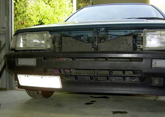
    I had a sheet of fiberglass left over from my failed parcel shelf glass job #3, anyhow by memory its 5 layers thick, so it can flex a little it's pretty tough. I layed on the ground marking it out a peice at a time with my marker and cut it with tin snips initially then a bench sheet cutter. After painstakingly getting the right size I used the 3 existing holes in the bottom lip of the bumper to bolt it down. I placed my fiberglass peice ontop of that lip and also used washers to secure it. Then in the middle I used the two mounting points the original engine plate used. On the bolts that used these I fitted an oversized washer and then places 3 lock nuts on it that wernt wound all the way down, that way the washer can still move but the bolt can be done right up because it hits the top lock nut, so the nuts act as a spacer to stop it getting pulled in too far. I am not sure how much this will do but I like doing this stuff as I know every little thing helps and it cost me nothing, a bit tedious though. As a bonus it looks profesional which is a bit of a suprise.


    Also on the same day I did a dummy fit of where I want to place my air filter, although I am undecided now for water reasons, see my forum thread on it here:


    anyhow heres a dummy run with it in place in roughly the right spot:


    did a quick drawing for an idea I had on a set of extractors. Seeing I am so desperate for that extra length on the primaries I came with this breifly:


    I would if I did this use every last bit of engine space I have, and I would flare it out to go close to the strut tower and strut brace. Basicly my aim would be the max length using every last bit of room I have, I think I would have to run some pretty elaborate heat sheilds too to protect everything. I know I wouldn't get it but I would want 0.8M of length in my primaries alone and still be a 4-2-1 system. But for now it's just an idea I am playing around with in my head, it would be interesting to try it though I think.
    30kw club

  2. #22
    Elite rthy's Avatar
    Join Date
    Dec 2008
    Name
    Leo
    State
    VIC
    Location
    Tulla
    Country
    Australia
    Posts
    7,308

    Default

    with a second 20V in my hands in a few days I am making plans for it. I will put in the engine I have now and in the meantime it looks like I am going to do some work on this one. Here's some of the ideas I have thought of:


    head:

    - Ported (mainly intake)

    - Match ported intake manifold

    - Combustion chamber de-shrouded a little.

    - Metal head gasket


    Bottom end:

    - Some 20V pistons I bought with only 40K on them balanced by myself

    - Cro-Mo rings

    - Con-rods linished and balanced by myself and shot peened by a friend

    - ARP Con-rod bolts

    - New bearings shells for Con-rods and main bearings

    - New main bearings

    - New main oil seals

    - Lightened flywheel by myself and maybe shot-peened by a friend

    - Fully balanced internals

    - Block honed if needed


    I want to be able to rev it to 9 all the time and not have a problem, apparently this lets me do this. I am unsure of a few things yet but I will ask people next time, I am out of time once again.
    30kw club

  3. #23
    Elite rthy's Avatar
    Join Date
    Dec 2008
    Name
    Leo
    State
    VIC
    Location
    Tulla
    Country
    Australia
    Posts
    7,308

    Default

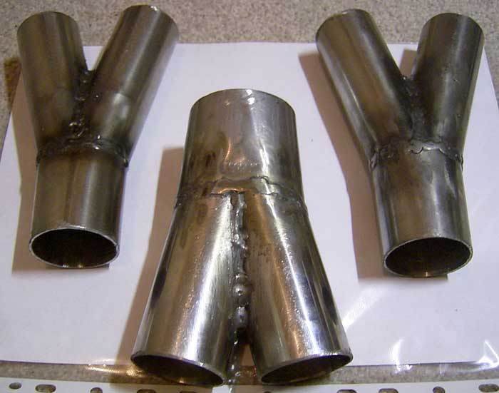
    I made some more collectors on the weekend:

    2 of (1.5 pipes into a 1.75)

    1 of (1.75 pipes into a 2.25)


    as usual they are made to a high standard (AKA bloody time consuming and tedious!!) and I am happy with them, my welding is a bit rough though, my welder is in desperate need of a service. I need one of every expendable part, my ceramic nossle insulator is literally in 2 peices jammed together.

    enough talk heres some pics:


    30kw club

  4. #24
    Elite rthy's Avatar
    Join Date
    Dec 2008
    Name
    Leo
    State
    VIC
    Location
    Tulla
    Country
    Australia
    Posts
    7,308

    Default

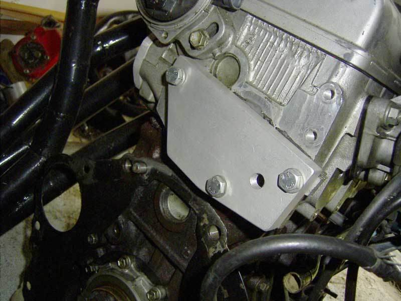
    I finished the main part of my rear water re-routing plate:


    The taped hole is for one of the two sensors the engine needs, I think I will fit the other one to the top outlet pipe of the engine instead.


    this is the rear water bypass plate with a test fit, fits perfect, yeah!


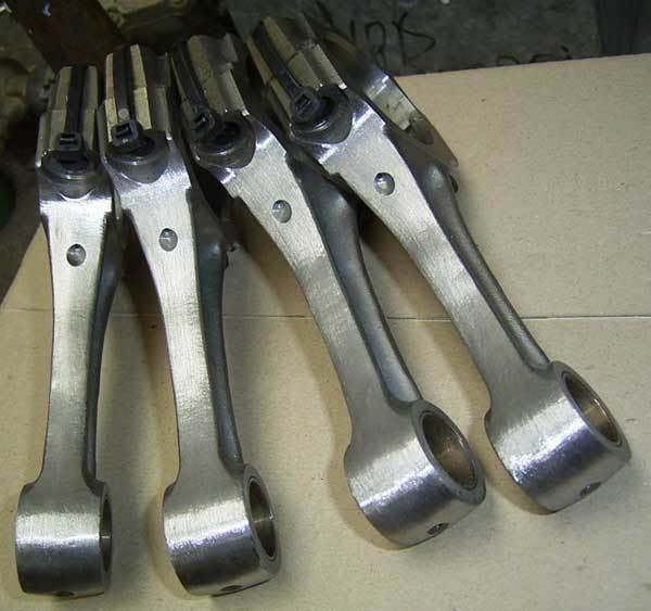
    also I finished the basic machining of my con-rods on my second engine:


    I will have to buy some scales and wait till my ARP bolts and ACL bearings come in before I continue. In the meantime I will probably give the rods a bit more of a sand down to make them smoother.


    Another side pic of the engine:


    this is my experimental trumpet setup that I am playing with:


    I will have to finish it off once the enigne is in so I know exactly how much room I have to play with. Looks like it might come a bit close to my braking system but I will do what I can.


    My extractor piping I used is 309 grade stainless, or atleast I think it is... the main supplier I have for this is Fast-fit mornington who are a great bunch of guys for real world answers. They however didn't have 1 3/4 pipe so I went to george archer metals in Dandenong, who were very cheap indeed.

    The primaries on my extractors are 1.5 inch (38mm) O.D and temporarily the secondaries are 2 inch. These will be changed to 1 3/4 soon enough.

    The reason I am lengthening to gain power in the top end, I would like to gain power down low but I don't have enough room available under the car to pull that off. Normally I would lose top end and gain low down power by lengthening my extractors however mine are way too short. I have been told the length I suits a harmonic resonance at 10,000 revs and a secondary resonance at 5000. So I really need the extra length to brind the tuned revs down further. Because I need such an obsessive amount of room to do it I will have to compramise. I will try hard to tune it for 6000rpm though and have a secondary resonance at 3000.


    another quick update:

    - I ordered these:

    * my TRD gasket from greenline
    * a new timing belt for the 20V, it's the same as a Lada Samara (thanks to Bill Sherwood for that info)


    - I also finally found aplce that can get me Cro-Mo steel pipe for a reasonable price. They are called aircraft metals in Tullermarine in Vic. They also have some Titanium plate that I am interested in...
    30kw club

  5. #25
    Elite rthy's Avatar
    Join Date
    Dec 2008
    Name
    Leo
    State
    VIC
    Location
    Tulla
    Country
    Australia
    Posts
    7,308

    Default

    I worked on some more of my RWD conversion bits today:


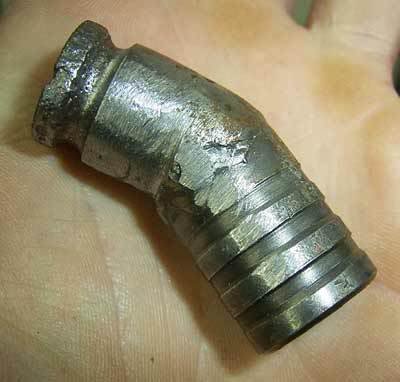
    I used this little jigger that was the to bypass pipe off a 4Ac which was chopped and welded to a section that grooves cut into it:


    which I then glued into this 4Ac water pump housing:


    apparently epoxy resin likes to get a bit soft after 100 degrees so I plan to drive this for a while and then try and reef this out with some pliers, that will tell me for sure.


    I finished my fuel pump mount for my car, I used a short length of cro-mo hollow square section for the main support, some stainless leftovers from my exhaust for the pump holder and some extra brackets off the side. It uses the two support bolts of the petrol tank and clears everything (I think!). I had to make it two peices because if it wasn't it would mean tottaly taking the supports off the fuel tank to fit it, which would mean someone holding it up. Instead of this I made it so firstly one side bolts in then the other and the two bolt together at one of the ends. This means it's quite easy to fit. I will also fit some soft rubber between the fuel pump and the clamp to shut the thing up. I allowed for this in the design of it. It is also held in a position where the lines should run without any trouble and out of the way of everything.

    Well enough talk here's some pics:


    I know this is an overkill but I like to do things right, I am sure this thing will never cause me any greif and it's easy to fit and remove, it should work great.


    heres another peice finished:


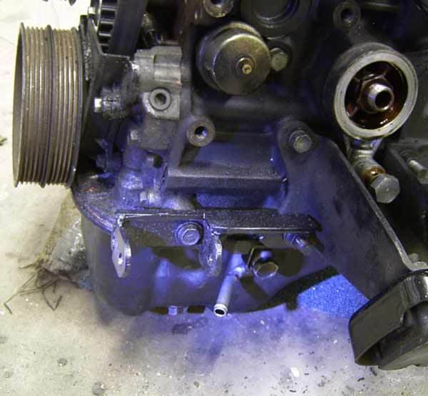
    This ones off a 4Ac for my custom cooling system, and has been modified to clear the knock sensor and also the throttle brace. I made up another brace for it so it doesn't put undue stress on the 2 studs that hold it on on the rear thermostat housing. it has also been painted in Satin black which is what many components will be.

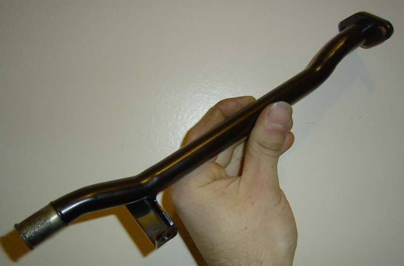
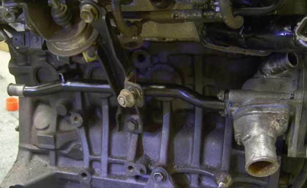
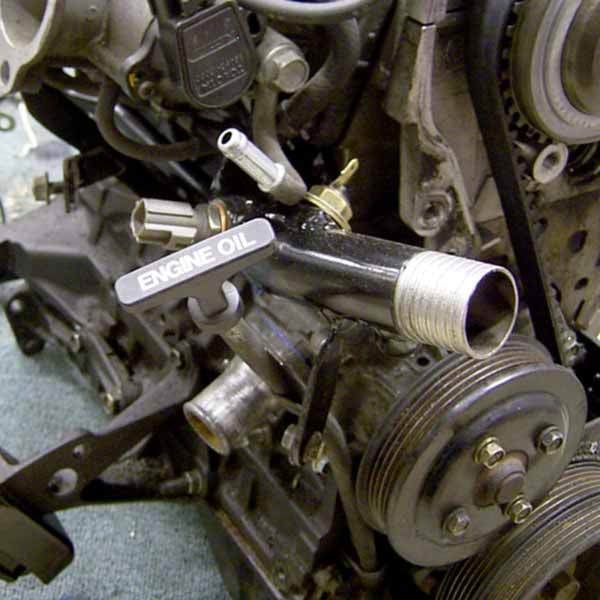
    Finally finished my handmade top water pipe, I now modified it to accept both sensors, ie: dash temp and ECU sensor.

    - Took my engine and trans out

    - Split and labeled the body loom (just a few wires)

    - bolted all my RWD water conversion pipes on my 20V, it looks great!

    - Swapped my standard Sprinter 13/16 both master brake cylender for a Landcruiser 15/16 item. I need to source a brake bias valve from somewhere before I make the custom lines to suit.
    30kw club

  6. #26
    Elite rthy's Avatar
    Join Date
    Dec 2008
    Name
    Leo
    State
    VIC
    Location
    Tulla
    Country
    Australia
    Posts
    7,308

    Default

    Another thing I have been doing is rebuilding my second 20V, I have so far taken almost all of it apart and I am sorting things out now. I also fitted my ARP main bearing cap kit and it fits really nice. More to come once I find someone who can do some machining for me in Vic, anyone know someone?


    Heres my specs I at this stage am aiming to get or have already:


    HEAD:

    - Matchported intake and exhaust manifolds
    - Ported intake and exhaust ports


    ROTATING ASSEMBLY:

    - All components fully ballanced
    - Con-rods linished, crack tested, shot peened and with ARP rod-bolts and ACL bearings


    OTHER:

    - Main bearing cap bolts replaced with an ARP main stud kit
    - TRD 0.8mm high compression metal head gasket
    - Knife edged throttle butterflies


    EXTRACTOR DIMENTIONS:

    - 1000mm long primaries
    - 500mm long secondaries


    INTAKE:

    - approx 200mm long inlet path with full bellmouth trumpets
    - 2+ liters volume intake airbox volume


    MANAGEMENT:

    - Wolf 3d ECU
    - 2 x M&W twin channel ignition modules
    - 4 x hyundai coils


    Well the time has finally come:


    This is the stage that I am at right now. My loom is in, the 4Ac is out, the 4AGE is in RWD form and the old alternator wiring has been taken out by myself (took a while).


    Bobski: Heres my master, anyone have any idea what it's off?


    Also notice my adjustable shockers and the plates that will be the start of the construction of my strut brace. A big thanks to Pete for those.


    and lastly a proper shot of my fabricated alternator bracket which still needs to be aligned:


    Last time I took my 20V out it had no engine hooks, so I ended up lifting it with a sling that went under the throttle bodies, yes I lifted the whole engine by the throttles! For bloody obvious reasons I wanted to avoid doing that again so I took the ones off the 4Ac engine and modified them to fit. Heres how they look:

    This one was shortened, had a plate welded on to extend it from the side and then redrilled:


    This one was chopped, extended and drilled:


    Also notice the rear transfer plate in place and the side outlet.
    30kw club

  7. #27
    Elite rthy's Avatar
    Join Date
    Dec 2008
    Name
    Leo
    State
    VIC
    Location
    Tulla
    Country
    Australia
    Posts
    7,308

    Default

    More of my RWD conversion bits:


    My modified 4Ac rear water pipe, this ones for my heater water supply.


    My custom water outlet pipe I made bolted in place. It was made to hold both sensors and to also hold the original 20V dipstick in place.


    Well at the moment my car is seriously pissing me off. It goes to show that no matter how carefully I plan things shit still happens. My airbox is useless, I couldnt syphon the tank out, my extractors cant be modified easy and have to be left alone, I dont have enough of the right materials to do the exhaust and the list goes on. Ontop of all that I have had time working against me even though I am having time off at the moment.

    Anyway it hasn't been all loses, I did get lucky with something:

    I was once again at Super Cheap Auto (love that joint!) and I looked through the pile of radiator/heater hoses and I found one that I thought I could use for my engine, It was off a Gemini. they also had a brass adapter to join the pipe. I took it home, chopped it in the middle, added the joiner, rotated it on the join 180 degrees, clamped it back up and then cut a shoprt section off one end. It fit like it was made for the job, not bad considering I didn't measure anything.

    Here is what it looked like after I modified it:

    rearpipe1.jpg[/img]

    For those who can't read it it says "heater hose to suit Holden Gemini", also included in the pic is the packet for the brass joiner


    this is how its meant to plug up:


    One end goes to the heater core water supply valve and the other to the outlet on the engine head.


    well unfortunetly my camera has died a quick death by the hands of salty water (don't ask) so updates might be a bit uninteresting for a while. I will try and borrow a camera when i do need it. A better one is on the way, so hopefully that means less grainy pics.

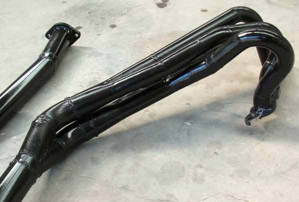
    I managed to finish my extractors, I am so pushed for space that I hammered the underside of the body a little and also couldn't fit a flange under there. So I will most likely have my extractors, the collector, the flex pipe and then at the end of the flex I will have a flange. Sprinters realy are shocking when it comes to room under them near the firewall. The reason I am cutting so close is because I am making sure that when I hit the subframe just behind the front wheels I want to make sure that it hits just that; the sub-frame, not my extractors. The whole system start to finish doesn't at any one point drop lower than the body of the car, quite a difficult thing to do I must say. This is the price I pay for having such a low car. Oh well it will atleast give me one less thing thats going to wreck my system.


    thought I would show up a pic of how my engine looks almost complete:

    30kw club

  8. #28
    Elite rthy's Avatar
    Join Date
    Dec 2008
    Name
    Leo
    State
    VIC
    Location
    Tulla
    Country
    Australia
    Posts
    7,308

    Default

    I managed to borrow a digital camera off a friend so I have pictures again after a while.

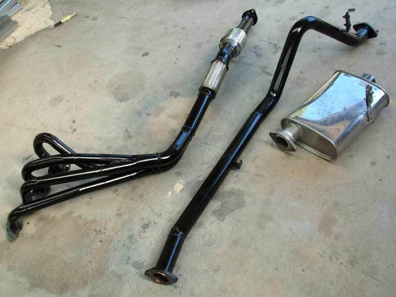
    after a huge amount of trouble my stainless exhaust is finally almost done. I still don't know if the pipes will crack with the steel welds but I am going to find out. I won't have pictures of it fitted under the car for a while but heres how it looks on the floor:


    notice the metal cat in the middle. It is the smallest size of 2.5 inch and I know it's a complete overkill but I mainly bought it for its size, thanks to John from Importbitz for that one. The pipe betwen the cat and the flex is actually 2.5 inch to suit the cat but it's been reduced to 2.25 on the other end and of course all changes in size are gradual and smooth.


    Heres my master cylender now connected up with some custom brake lines (thanks once again to Rowvile brake and clutch):


    I sure hope I got it right with which pipe goes where. I would assume it's the same setup as the sprinter but you never know.
    30kw club

  9. #29
    Elite rthy's Avatar
    Join Date
    Dec 2008
    Name
    Leo
    State
    VIC
    Location
    Tulla
    Country
    Australia
    Posts
    7,308

    Default

    I have now also finished my airbox, this is what I managed to do previously:


    and I thought I couldn't use it because I didn't have the room. Well I managed to fit a banjo fitting on the master cylender and I also came up with an airbox design that allowed enough room for it. So heres how I started:


    and with the trumpets in place:


    this is how it turned out:


    it turned out way better than I expected. Usually anything i make is more shonky looking than this so I suprised myself. I will have to wait to see if I allowed for enough room for the engine to rock side to side.

    The box did however warp when I made this and it doesnt sit that well anymore on the rubber seal. I am hoping that it will seal ok when the bolts pull it down when I tighten it up.

    I also need to drill some of the original nuts out and weld them in the top instead, this is because I can't access the top anymore to do up the originals, I will have to do it from the bottom.


    This is however still only a temporary setup, i plan to have a low mount airbox with long trumpets feeding it, but that's later on.


    and finally how my engine is looking now:


    unfortunetly me doing everything myself also has it's downsides, I have a limited amount of time and my neighbour is about to go on a rampage that's enduced by permement grinder sounds coming from my garage on a Saturday. Unless your a car fan or have a hearing problem you dont want live near me!


    making some progress, still a bit slow though:


    - Driveline is back in

    - Airbox is almost ready

    - Experiencing problems with my fuel tank mods

    - Exhaust is mostly in but waiting on having an oxy sensor plug welded on.

    - Wiring almost done... I think
    30kw club

  10. #30
    Veteran obey wan boenny's Avatar
    Join Date
    Dec 2008
    Name
    Ben
    State
    SA
    Location
    Adelaide
    Country
    Australia
    Posts
    1,813

    Default

    holy crap talk about custom.. please keep us updated, this build is very interesting.

Page 3 of 25 FirstFirst 1 2 3 4 5 6 7 8 9 10 11 12 13 ... LastLast

Similar Threads

  1. Parting out: Silvertop 20V AE71 Spirit project - Pics added
    By beerhead in forum Car Parts For Sale
    Replies: 20
    Last Post: 31st July 2007, 03:50 AM
  2. tech question: DIY 4age cut n shut inlet manifold?PICS
    By slidn70 in forum Technical - Questions
    Replies: 2
    Last Post: 20th June 2007, 01:56 PM

Posting Permissions

  • You may not post new threads
  • You may not post replies
  • You may not post attachments
  • You may not edit your posts
  •