Page 5 of 25 FirstFirst 1 2 3 4 5 6 7 8 9 10 11 12 13 14 15 ... LastLast
Results 41 to 50 of 244

Thread: Project Q - Sams 86 (many tech Pics)

  1. #41
    Elite rthy's Avatar
    Join Date
    Dec 2008
    Name
    Leo
    State
    VIC
    Location
    Tulla
    Country
    Australia
    Posts
    7,308

    Default

    I managed to start some minor porting as shown below:


    As the picture shows I took some material off in and around the exit of the inlets where there were a few machining burrs and a bit off the valve guide support casting that I took care of with a multi-tool. I could of used my die grinder but I wanted more precision and didn't want to slip.


    Note: It is bloody hard to take good pics of the inside of an inlet port.


    On the weekend however I did some more serious work. I used my die grinder with a carbide burr and ground down the lump of metal behind the valave guide even more till it resembled a ramp shape.

    I also ground down the valve guides a bit so as to not have a large flat area on the top, so on the edges they have been sharpened now. I will get a pic of this when I manage to do so.

    Lastly in the porting I noticed that the inside diameter of the valve seat insert in the head for the two exhaust ports was less than that of the the ports hence leaving a step. I have only done two ports but I ground this out to make it even, should help things a bit.


    Also I did something very experemental; I noticed a while back that the top of a 20V inlet manifold has a high section to suit an injector and it really doesnt line up with the head as shown below:


    The red dots show the shape of the head as it lines up.


    and here is the head:


    I scribed an outline that shows the inlet manifold as it matches up. Its not hard to see that it's one hell of a step to have in an intake. When I talked to people about matching this they all took a step back and said 'noooo' reasoning that its there to create turbulence or something to cause atomisation. I talked with my friend who has been working on race cars for a while now and he said to go for it, so I did. It took quite a while and I need to still do some finishing but the result sure is something:


    I will do some more work soon.


    heres one will freak out many people: I am thining of ditching anything 4age, I don't like dealing with such old technology and I want some thing from .. wait fot it:

    HONDA!!!

    I am doing research into fitting a F20c out of a Honda S2000 into my car. I have already talked to my engeneer about it and he thinks its an awesome idea and he insisted I do it, so much for the staight faced stereotype... So if I do this I will be australias first fully legit F20c sprinter, maybe just the first one in general but someone must of done it by now
    30kw club

  2. #42
    Elite rthy's Avatar
    Join Date
    Dec 2008
    Name
    Leo
    State
    VIC
    Location
    Tulla
    Country
    Australia
    Posts
    7,308

    Default

    I found some more useful links:


    a seam weld job in Volvo:


    I am looking into to doing some serious bracing on this thing so I have started looking for info.


    Another F20c into 86 conversion page:


    I managed to do some more work on my strut brace, I intitually started with some plain pates as shown in this pic bolted to the top of the strut tower on the left:


    these two rings were made of 3mm thick stainless plates and were quite heavy. While the holes where in the right spot I had to do some heavy die grinding to bring them to fit on in relation to the middle hole.

    After this I started to drill holes to lighten them and I also welded on two cro-mo tubes in short vertical section, these will be taking the lateral stress. These are 22 x 1.5mm. I also removed the un-needed material, filed the welds and lastly shot-peened it so it would paint better later on. Interestingly even though the stainless is much harder than normal steel it had a dimpled effect from the shots while the Cro-Mo tube had next to nothing, no wonder it's such a bitch to drill through. Heres how they ended up looking:


    In a little bit of free time I managed to shape one of my Cro-Mo bars for the main sections. This is thinner while still having a 22mm diameter it only has a 0.9mm wall thickness, it doesn't sound like much but it is Cro-Mo and I have a unique idea in mind.


    this first piece has purposefully been kept as straight as possible for rigidity and goes directly to the tube above one stud. It will be braced more at each end and this I hope will trasfer the stress directly into each stud. I am not going to reveal the design I am using for the main section yet, but instead just keep posting pics as I work on it. I will say though there is a second reinforced pipe going across as part of the design.


    I managed to have a small set-back the other day. After doing something I won't name I heard a real loud ticking noise from the engine, for a moment I was thinking "hmm, I must of broken something inside the engine, oh well" but then I recognised that it was the sound of an exhaust leak. Looking under the bonnet I saw that one of my primary pipes had completely broken off the flange and there also was a crack under number two. A friend saw this and said it was because I didn't have a brace from my trasmission to the bottom of the extractors, I don't know if this is right but it sounds right so I will make such a bracket in a the near future. Heres where it cracked:


    I took the pipe off and welded it back up mostly using a Tig but I used a Mig for where the Tig wouldn't reach and I have since put it back on the car without any more issues in that area.
    30kw club

  3. #43
    Elite rthy's Avatar
    Join Date
    Dec 2008
    Name
    Leo
    State
    VIC
    Location
    Tulla
    Country
    Australia
    Posts
    7,308

    Default

    I borrowed an electrical pipe bender from my work to do the second pipe of my strut brace, not the first time I have used one of these benders for a project. It only needed a slight bend either end and is yet to receive the reinforcing supports because I am still making them. It also still only has temporary welds holding it together for now.

    It was far from easy to do though as the first bend I did kinked straight away, so at each end I had to bend in two close together sections. Heres how it looks:


    All in all it has been a very tricky project but so far the work has really been worth it seeing that it's rock solid and weighs under 1.5kg so far. I still have a fair bit more work to go though.


    this is one of the flat sections of plate that I used to make my brace before I welded it:


    It took me a considerable amount of experimenting to make these pressed holes properly. Using a lathe I made up a special die and 2 punches to get the right shape. I did it with one punch initually but the force on the metal was too mcuh and it was warping the steel, so I made a starter puch that had a gentle angle. I can post some pics of this if people want to see it. To punch these holes the way that I decided to do in the end I have to follow these steps:

    - Mark out holes 30mm apart on some steel

    - Center-punch

    - Pilot drill small hole

    - Drill a hole a 13mm hole

    - Deburr hole

    - Place my die under the hole, and place the starter punch into the hole

    - Using a press push the starer punch in and remove

    - Change to the finishing punch and press


    All this about 50 times, oh yes I am patient, but I can do it pretty quick now.

    One of the problems I had was that I couldn't drill a 13mm hole into the sheet metal, if it wouldn't make a triangular shaped hole it would rip at the steel, try and pull it out of my hand and leave a rough hole. So what I did is regrind the tip of a drill bit to have a very sedate cutting profile on the tip, you could almost call it purposefully bluntening it. After I did that it would slowly cut through and leave a perfectly round hole without ripping at the material when it went through.

    Regardless of how I acheived it the results I was quite happy with. During my trial peices I would start with a floppy peice of sheet metal and once I had stamped all the holes it would become quite rigid, and all while I had actually removed material from the sheet... funny


    My strut brace is now finished and bolted up, i will have pics soon.


    Also for anyone who is interested I bought my Cro-Mo from a place called Airport Metals. There are very few places selling 4130 grade steel so I thought I would post the info here for anyone else who is interested.

    Airport Metals
    26 Lillee Cresent
    Tullamarine Vic

    (03) 9310 5566


    They also sell some other exotic materials like 6013-T4 Aluminium, Titanium and even Hastelloy.


    now for something different, I did this a while back but I might as well post it seeing its related to my car and someone might like the idea.

    When I was living at my previous place I found I needed alot more light to work on my car so I was going to buy a worklight from the warehouse. Finding that they only had high wattage hallogen fittings at the time I decided to make my own. I bought a pair of batten holders and spent some time designing something. I decided that not only would I have something that could be adjusted to light up my engine bay it would also be adjustable to fit under a car or over it. So I bought one tiny normal castor wheel and two slightly larger castors with a brake on them from Supercheap auto. I made up most of it in an afteternoon and wired the rest up later. I initually only wired up two globe fittings due to a shortage of batton holders at The Warehouse store and I also used energy saving globes for a nice white light. The next day after leaving it at my place I found my other roomate at the time using it to paint part of his car, so he obviously liked it. With the four fittings now in place it is a bit bulky but it does a very good job and I use it all the time. Also as a bonus it cost me like under $30 for everything. Heres some pics:


    30kw club

  4. #44
    Elite rthy's Avatar
    Join Date
    Dec 2008
    Name
    Leo
    State
    VIC
    Location
    Tulla
    Country
    Australia
    Posts
    7,308

    Default

    took a pic of my brace which I installed this morning.


    it ended up stronger than I expected, when I try and push it with all my weight I can't feel it flex even a few mm .

    Also the final count for the weight is: 2.4KG!!!


    Needless to say I am pretty happy with this.


    I haven't been able to work on my car much lately but I have done a few smaller things on the side:


    - I now have made a small batch of RWD 20V bypass plates which are for sale for $50 each. Also I will be making side plates shortly.


    - I have continued to work on my own home-made gaurd roller. I have drilled out a huge plate for the hub and the roller is bellow.


    - I managed to buy a pair of Corona XT-130 lower control arms from the wrecker, i will be fully repainting and reconditioning them. I have already pushed the bushes out, ground off the steering stopers, pushed the ball joints out, cleaned + sanded + painted them, fitted new ball joints and I am working on doing the bushes. Heres how one looked when i bought it:


    Hopefully it will look like new once I am done.
    30kw club

  5. #45
    Elite rthy's Avatar
    Join Date
    Dec 2008
    Name
    Leo
    State
    VIC
    Location
    Tulla
    Country
    Australia
    Posts
    7,308

    Default

    right now my sprinter is no longer running. I was doing some wiring and somehow I killed my DLI module. I dropped it to the guy who built it and he currently looking into it. Other than that I still managed to do some work:


    I reran the wires for my coilpacks and also cleaned up my relay/fuse panel.


    and I finished my lower control arms:


    I did the following:

    - Started with XT130 arms
    - Chopped off the steering stoppers
    - took the ball joints out
    - took the bushes out
    - cleaned them
    - painted them
    - pushed new ball-joints and bushes back in

    I hope to install them soon, also they cost me a total of $35 each!
    30kw club

  6. #46
    Elite rthy's Avatar
    Join Date
    Dec 2008
    Name
    Leo
    State
    VIC
    Location
    Tulla
    Country
    Australia
    Posts
    7,308

    Default

    well I have had my car off the road for 4 weeks, I was doing something to the wiring and the car no longer ran. I changed one busted Magna ignitor and it idled but couldnt rev. I ended up talking to the guy who made my custom DLI module and he modifed the module to get a square wave signal directly out of the ecu instead of off the crank angle sensor. So I now have 2 wires coming directly out of my ECU going to my DLI module. It runs great again but I still don't have a tacho, I will look into it more.

    Also a bit of a setback on my other engine I am building I found this:


    its a con-rod bearing and it has scored the crank. I have no idea how it happened but I guess I will have to get it ground and have oversized bearings fitted.
    30kw club

  7. #47
    Elite rthy's Avatar
    Join Date
    Dec 2008
    Name
    Leo
    State
    VIC
    Location
    Tulla
    Country
    Australia
    Posts
    7,308

    Default

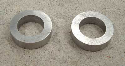
    I took my suspension out and I changed my lower control arms and also installed these lock spacers:


    notice the difference in length between the corona ones and the sprinter ones:


    10mm apparently.


    Heres how it looked installed:


    I am going to post a guide soon on how I installed these lock spacers.
    30kw club

  8. #48
    Elite rthy's Avatar
    Join Date
    Dec 2008
    Name
    Leo
    State
    VIC
    Location
    Tulla
    Country
    Australia
    Posts
    7,308

    Default


    Lock spacers (as shown below) are a small spacer that goes onto the end of the steering rack shaft on either end. It allows the steering arms to move further into the steering rack to allow for more lock. I have been told it gives about 7 degree more angle with the spacers I used and it reduced my turning circle by about half a meter. It is a very cheap upgrade at $25 to $30 or easly machined if the option is there. This will push your tow right in so a wheel alignment is really needed a short time after having this done. Unless there is some damage or a different set up is used then there should be enough factory adjustment in the steering arms to allow for it. It isnt necessary normally to remove the steering arms or rods to install these.


    Here is how I installed mine:


    Looking under my sprinter this is how it is standard, It has the rubber steering boot on either end of the steering rack with a clamp on either side.

    - Undo the first clamp (1) with a screwdriver, can be real hard to get to.
    - Using some plies squeeze the second clamp (2) and slide it off
    - Slide the rubber boot off as much as possible


    This is what you end up with after the boot is slid down, the end clamp (1) can be left in that position, the boot needs to be slid off the end of the shaft (to the right for the drivers side), to do this it may be needed to remove the steering rod clamp (5) to fully slide the boot out of the way. Alternatively a second person could hold the boot to one side while the rack is being worked on.


    With the boot moved to one side the rack end ball joins are revealed. To undo the rack end two spanners are needed. I found however the locking tab (2) was getting in the way of my spanner so I bashed it out of the way.

    - If locking tab (2) is bend over the flat secttions of the rack end then bend it away using a screwdriver and a hammer as done so in the picture. When taking the rack end off care must be taken to not twist the steering rack in any way, putting force on this may well damage the steering rack.

    - Place a 24mm spanner on the steering rack flat section (1)
    - Place a 30mm spanner onto the rack end ball joint (3)
    - While holding the 24mm spanner still, turn to undo the 30mm spanner
    - Completely remove the ball end and throw away the locking tab (2)


    Some locking compond suck as Loctite is recomended for the rack end because the ball joints previously has a locking tab as a saftey but this can no longer be used.

    - Place the lock spacer onto the thread that is on the end of the steering shaft
    - Use some locking compond onto thread
    - Screw ball joint back onto steering rack
    - Tighten and re-assemble in reverse order as earlier and repeat process for other side.
    - Get a wheel alignment
    30kw club

  9. #49
    Elite rthy's Avatar
    Join Date
    Dec 2008
    Name
    Leo
    State
    VIC
    Location
    Tulla
    Country
    Australia
    Posts
    7,308

    Default

    well its been a while since I managed to do some work. Anyhow my coil mount broke once again and I decided that I was going to fix the problem once and for all. I not only moved the coils to the top of the engine but I modified the top cover to fit on and I also fitted the front covers which I painted black. I still need to paint my cams cover, I am not pretending to be a blacktop I just don't like silver on an engine much. I resized some OEM 20V leads for the job which I am a bit unsure about.


    My coils mount is very simple but I still like how it turned out.
    30kw club

  10. #50
    Elite rthy's Avatar
    Join Date
    Dec 2008
    Name
    Leo
    State
    VIC
    Location
    Tulla
    Country
    Australia
    Posts
    7,308

    Default

    well its been a while and a hell of a lot of crap has happened, heres how it started:

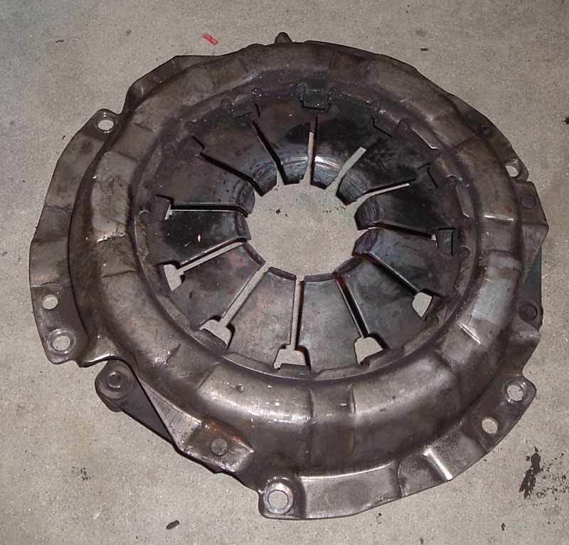
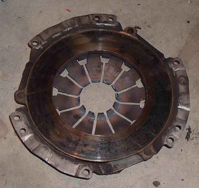
    I was driving along minding my own buisness and I went to change gear, it didnt feel right, I pressed it again and my foot went straight to the floor with ease, I knew something was up. Just by chance the Moomba celebrations were on and I got stuck in traffic without a clutch. I ended up driving it without a clutch but I had to start and stop a few times, this made my starter motor so hot it started to smoke. I drove 40km home and looked at it the next day. I found the slave cylender had popped out, no big deal I thought. When I had a closer look i found that the clutch fork was out. I took off my T50 box and to my horror I saw this:


    the thrust bearing was seized and rubbed against the pressure plate till it melted, it used to be an exedy, what a loss!!! The weird thing is I didnt hear a thing and I didnt have the stereo on at the time.


    So first up I broke:

    1: slave cylender
    2: thrust bearing
    3: excedy pressure plate

    the thread is on toymods for anyone who wants a read:


    A very short time later I was driving along and again my foot went straight to the floor, getting really pissed off I kept driving but I started to hear a knocking sound. I stop look under the car and stunned I se my brand new PBR slave cylender hanging down. Looking closer I see that its legs have been broken off. When I later was able to take it out again I had a good look and found it had a casting failure. I took it back, got another, and reinstalled it. Back on the road again

    Failure 4: brand new slave cylender


    a few more days pass and once again I press on the clutch to hear a metal rubbing sound, pissed off I decide to drive home anyway. When I take the gearbox off once again I find that the brand new thrust bearing was seized WTF!!??? onto of that it has wrecked my fork and clips. I get a new bearing (a nachi one this time), another fork and some new clips and I am on the rroad again.

    Failure 5: brand new thrust bearing
    6: thrust carrier retainer clips
    7: clutch fork


    at this stage I am rather cranky and I have a good week without a problem, I continue to work on the car I am fixing for my partner and I manage to get a roadie, all I need to do is go back for a final check and get it signed off, I get about 10km away before the engine seizes up.

    Failure 8: 98 model injected charade engine with only 130K on it ....$$$$!!


    more weeks pass and I think I am set for a little while, oh boy was I wrong...


    some fool without insurance decides to not look or give way in a round-a-bout...


    damaged parts:

    - sub frame
    - headlight
    - bonnet
    - JDM grill
    - gaurd
    - parker
    - bumper


    an interesting note is that while I had only third party with Just car they are sorting it all out and sending the guy the bill.
    30kw club

Page 5 of 25 FirstFirst 1 2 3 4 5 6 7 8 9 10 11 12 13 14 15 ... LastLast

Similar Threads

  1. Parting out: Silvertop 20V AE71 Spirit project - Pics added
    By beerhead in forum Car Parts For Sale
    Replies: 20
    Last Post: 31st July 2007, 03:50 AM
  2. tech question: DIY 4age cut n shut inlet manifold?PICS
    By slidn70 in forum Technical - Questions
    Replies: 2
    Last Post: 20th June 2007, 01:56 PM

Posting Permissions

  • You may not post new threads
  • You may not post replies
  • You may not post attachments
  • You may not edit your posts
  •