Reply With Quote
Some turbos are water cooled and others are not which turbo do u have


Gents,
I've recently replaced the water lines going to my turbo on my 4agze (AE101) turbo set up and was wondering which way the water is flowing through the turbo.
Some say there is no specific water outlet or inlet on a turbo but I believe there is due to the thermal siphon effect.
Having said this I want to make sure my lines are connected the right way so this effect can occur.
The line from the low side of the turbo is T'ed into a line that on one end is connected to the valve that is operated by the heater control dash. The other end of that line goes to, which I believe is, the external thermostat.
The line from the high side of the turbo is T'ed into a steel line that runs on the right side of the engine (when sitting behind the wheel and looking forward) which I believe is the water outlet from the head. This steel line is then also connected to the external thermostat (with a rubber line).
Can someone tell me which way the water is flowing? Am i correct in assuming that the water coming from the head is my water feed for the turbo?
ADM AE86 Levin

Some turbos are water cooled and others are not which turbo do u have
My AE86 4AGZE to 3SGTE thread
Check out my sale threads for 4age and ae86 parts
http://www.ae86drivingclub.com.au/fo...nd-going-Turbo
http://www.ae86drivingclub.com.au/fo...ything-must-go
Sponsors
Platinum Automotive Smash Repairs - Padstow

I just wrote a long response and realised I had contradicted myself. However I'll link to an interesting and relevant document. Especially the top of page 7.
Last edited by Hen may possibly be a nut; 11th August 2013 at 01:54 PM.

Off topic, but not quite true. Popular consensus is that ball bearing turbos NEED water while plain bearings don't care too much even if they are water cooled. The reason being that ball bearing turbos have a far smaller passage for the oil to pass through and is easier to burn the oil up causing coking. Plain bearing turbos have a greater oil clearance and oil can still flow through without absorbing too much heat and coking the centre section. Either way, the car should be cooled off before shutdown after any high-load driving. I prefer load load driving to get air through the rad and oil cooler to turbo timing.
Water cooling does make a turbo last longer though.
Oh, what I just typed is covered by the paper Hen posted up. Pretty interesting reading considering OEM turbo is not set up like that in S-chassis cars. I always wondered why one side of the water jacket was higher than the other.
Gents,
I understand the working of the thermal siphon effect so that wasn't really my question. Nevertheless it is interesting info so thanks for posting.
My turbo type isn't really relevant but I have a gt28 from a jdm s15.
Perhaps I was somewhat confusing with the way I wrote my question but what I basically want to know is; what route does the water flow on a ae101 4agze. This way I can determine which line is my water feed and which is my water return.
ADM AE86 Levin
should help.
It sounds like your two water lines are connected to essentially the same point in the water system (both lines are close to the thermostat housing, on the engine side of the thermostat). Plus if you T into the heater lines AFTER the heater valve (as in between the valve and thermostat housing) then turning the heater off may also turn water to your turbo off.
Yeah i've seen that picture but couldn't really figure out which way the water the water is flowing taking into account the path of least resistance.
To add to that the turbo has been functioning fine so I would think the current situation works however I want to make sure and get a better understanding of how everything is connected as I did not build it myself
ADM AE86 Levin
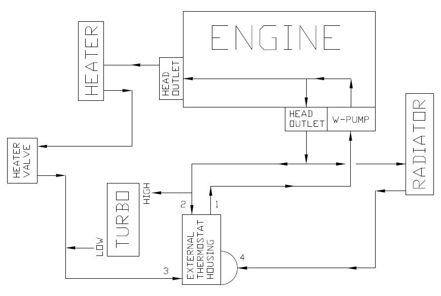
I've sketched up my situation and added arrows for the flow directions. The flow directions are based on the info I could find so far. Please see image below.
I assume the flow directions are correct, can someone confirm this?
Starting at the waterpump which sucks water from connection 1 on the external T-housing and pumps the coolant through the head and out the two head outlets.
Assuming the following I think the lines are connected the wrong way around for the thermal siphoning effect to occur:
- There is pressure between the head outlet on the side of the engine and connection 2 which pumps water into the turbo via the high side.
- There is suction on the low side of the turbo due to the water pump sucking water from the external thermostat housing.
Disregarding the fact that the lines might be the wrong way around I still have doubts that the current set-up actually works (although I've driven it ±5000 km's with no problems so far). Reason being that in my opinion there can be water pressure on both sides of the turbo...
Because in my understanding the thermostat in the external housing only blocks connection 4 so the waterpump can effectively suck water from connection 2 & 3. However if the heater valve is open there might also be pressure in the line between the valve and connection 3 because it is pumped through from the outlet on the back of the engine head.
Although one would also have to take into account the resistance created by the heater core and line diameters. I don't not know when does pressure in the line switches to suction.
Considering the current set-up was working I think switching the lines around would be the solution as the feed will be on the low side and the return on the high side.
Tried to make it as clear as possible so hopefully it is. Any help/input would be appreciated!
Last edited by Bozu; 13th August 2013 at 03:17 AM.
ADM AE86 Levin

Usually from factory, going by your diagram, you would swap the heater valve and the heater core around....
So the outlet on the back of the head, its first point is the heater tap/valve, then the heater.....
Iam not sure it would make a huge differance to function tho.....
Last edited by maxhag; 13th August 2013 at 01:05 PM.
1974 MX22 MARK II CORONA HARDTOP COUPE - Awaiting a full restoration
 Posting Permissions