


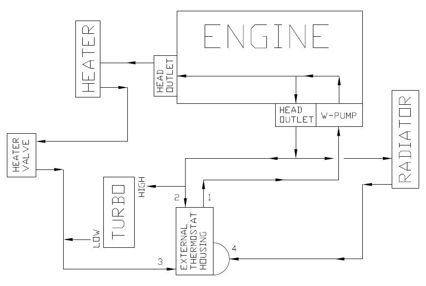
I've sketched up my situation and added arrows for the flow directions. The flow directions are based on the info I could find so far. Please see image below.
I assume the flow directions are correct, can someone confirm this?
Starting at the waterpump which sucks water from connection 1 on the external T-housing and pumps the coolant through the head and out the two head outlets.
Assuming the following I think the lines are connected the wrong way around for the thermal siphoning effect to occur:
- There is pressure between the head outlet on the side of the engine and connection 2 which pumps water into the turbo via the high side.
- There is suction on the low side of the turbo due to the water pump sucking water from the external thermostat housing.
Disregarding the fact that the lines might be the wrong way around I still have doubts that the current set-up actually works (although I've driven it ±5000 km's with no problems so far). Reason being that in my opinion there can be water pressure on both sides of the turbo...
Because in my understanding the thermostat in the external housing only blocks connection 4 so the waterpump can effectively suck water from connection 2 & 3. However if the heater valve is open there might also be pressure in the line between the valve and connection 3 because it is pumped through from the outlet on the back of the engine head.
Although one would also have to take into account the resistance created by the heater core and line diameters. I don't not know when does pressure in the line switches to suction.
Considering the current set-up was working I think switching the lines around would be the solution as the feed will be on the low side and the return on the high side.
Tried to make it as clear as possible so hopefully it is. Any help/input would be appreciated!


 Reply With Quote